Understanding and avoiding of eccentric loads
Eccentrical loads in presses often stay unrecognized and lead to unplanned downtime. This small report shows tools and solutions, that help to avoid this problem in your shopfloor.
Forming machines transmit huge motor output via transmission, bearings and guidances to the tools and process. In daily usage, machines are characterized by the nominal (maximum-)force, the maximum ram travel and the table size. There is a silent agreement, that the nominal force should be applied through homogeneous pressures under the ram with no eccentricity.
Obviously, the vendor makes specifications and limitations concerning the eccentric loads for proper design of critical machine components. Typically, some type of limit load curve is derived of these boundary conditions. Under this curve, secure machine usage is expected. This chart depends on the machine type. Of course, vendor specific design philosophies express themselves in this curve.
Well presented data make the daily work of setup staff easier and more efficient.
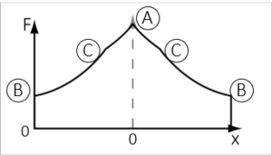
The picture right shows an example of a limit curve for a mechanical press with two connecting rods in feed direction. Practically, this chart is called tilting diagram, pagoda diagram or tent roof chart.
The horizontal axis represents the length of the press table between the pressure points, whereas 0 is the middle of the table. In vertical direction the force values of each load situation are plotted. This means, every load situation during a process leads to a dot, which describes nominal value and location of the representative force from the tool region. Independent of the machine design, the following characteristics are true:
- High resulting pressure force must be located above the middle of the table (A).
- The force center may not exceed the position of the pressure points (connecting rods) (B)
- The limit curve within the working region of the machine depends on the machine design (C)
Process understanding grows automatically if data and process behavior are fitting plausibly.
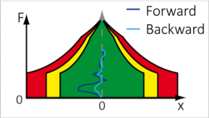
The chronological progress of the process results as a line in the chart, if momentary loads are connected with. A 100 % symmetrical process would run vertically up and down in the chart. Practically every process shows deviations from the perfect symmetry. Especially multistage processes have a tendence for extensive eccentricity due to the different process stages. The forward and backward movement of the ram typically leads to different paths. This is a result of the forming work, that is performed during the forward movement.
Of course, these effects are known and typically discussed and in best case sufficiently considered during purchasing process of machines. In daily business on the shopfloor, these considerations are mostly not applicable. Best practice is to check eccentricity of the maximum force.
Long years of IoT experience enables us to bring the right data in the right representa-tion to the right moment at the right place.
The experience of countless measurement tasks and continuous long-standing attendance of machine equipment shows, that surprisingly high eccentric loads appear unwanted and more frequently than one should think. The setup of often complex toolsets with multiple touchpoints, pusher and gas springs is not feasible based on load information. Setup staff does have small - and in many cases not any chance to recognize these critical loads. Typical setup strategy for these cases is diagnostic on parts, usage of spotting paper between distances, judgement of maximum forces and searching for pressure curves in the machine control. In a nutshell the responsible employee has to gather fragments of information from different sources and constructs a picture of the situation with unsuitable tools.
Based on quality measured values and knowledge of the pagoda curve it is comparatively easy to present the eccentricity of every stroke impactful by a characteristic line within the pagoda diagram. This enables staff to use existing up wedge shoes, adjusting foils or gas springs in order to “drive the process in the center” und bring machine loads into the specified region.
We provide ready to integrate solutions for your production.
The package of ConSeses for this case is:
Supplementary, we always recommend an acceleration transducer at the ram, in order to take dynamic behavior of the process into account, that may result from cutting impacts or contact of the ram before the air is pressed out of bearings.
One-point data acquisition and multipoint usage is the special charm of this approach. By using the same data at several points, communication becomes better and potential for conflicts is erased systematically.
The special charm of this solution comes fully to live, if greater optimizations are done on the same database. The tool design can use the characteristic eccentricity charts of critical tools in order to make tool enhancements or motivate setup guidelines for setup staff.
Typically, a mutual, fact-based language comes up after a short while between departments. This leads to more focused and goal-oriented cooperation.