Standardized load scenarios and mechanical characterization
The quality and precision of forming processes depend decisively on the mechanical performance and condition of the machine used. Especially in demanding forging, cutting and forming processes, the reaction of the machine used to different load situations is of central importance.
In order to systematically record these aspects, the term "machine fingerprint" has become established among our customers . The machine fingerprint refers to the unique, quantified signature of a machine that is derived from its reaction to a series of standardized load cases. On this page, we explain how we create the standardized machine fingerprint for forming machines, which measurands and operating conditions play a role in this, and what insights can be gained from it for process optimization, quality control and the machine design cycle.
Basics of Machine Fingerprint
The machine fingerprint is a measurement data profile that describes the mechanical properties of a machine depending on standardized load situations. The basic idea is analogous to biological fingerprints: Every machine has characteristic properties that can be systematically worked out and recorded. The fingerprint is a set of key figures and diagrams that depict not only the instantaneous performance, but also the stability and behavior under varying loads.
| ID | Feature | Significance | Measurement methods |
| 1 | Compliance | Deformation as a result of a load | Dynamic position measurement depending on imprinted forces |
| 2 | Damping | Decay behavior of vibrations | Swinging cycles, cooldown duration after impact |
| 3 | Tilting | Robustness against off-center loads | Position measurement as a function of off-center ap-plied loads |
| 4 | Natural frequencies | Resonance frequencies and amplitudes | Frequency analysis in open and closed state |
Standardized load scenarios for forming machines
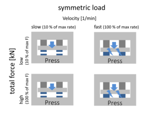
In order to create a comparable and reproducible fingerprint, a standardised procedure is required. Since the machine fingerprint is intended to reflect the behaviour of systems under operating loads, all measurements are carried out in automatic system operation under gradually varying load situations. For statistical validation, the dispersion of the recorded forces and stroke rates is recorded during the measurement. Only if the dispersions are within an acceptable range is the measuring point adopted as valid, otherwise the measurement setting must be checked and repeated:
Execution of the machine fingerprint
Symmetrical load
- Objective: Determination of stiffness, damping, natural frequencies under symmetrical load.
- Procedure:
- Reference load cells are positioned directly under pressure points
- the system is operated in different stroke rates up to the maximum speed.
- To imprint defined forces, the ram adjustment is gradually adjusted or material is placed under it until the desired load ranges or the nominal capacity of the system is reached.
- Setting variables:
- Stroke rate
- Pressing power
- Measurands:
- Reference forces from the press room
- Measuring Forces – Equipment Force Measurement
- Accelerations on the ram
- Positions in 1,2 or 4 positions
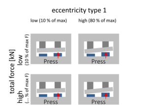
Off-center load type 1
- Objective: Determination of the system reaction, system measurement technology for off-center loads
- Implementation:
- Reference load cells are positioned directly under pressure points
- Reference load cells are moved off-center on one side
- the system is operated in different stroke rates up to the maximum (or fixed limit) speed.
- To imprint defined forces, the ram adjustment is gradually adjusted or material is placed under it until the desired load ranges are reached.
- Setting variables:
- Stroke rate
- Pressing power
- Eccentric force right/left, front/rear
- Measuring variable:
- Reference forces from the press room
- Measuring Forces – Equipment Force Measurement
- Accelerations on the ram
- Positions in 1,2 or 4 positions
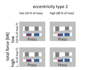
Off-center load type 2
- Objective: Determination of the system reaction, system measurement technology for off-center loads
- Implementation:
- Reference load cells are positioned directly under pressure points
- Reference load cells are placed on one side
- the system is operated in different stroke rates up to the maximum (or fixed limit) speed.
- To imprint defined forces, the ram adjustment is gradually adjusted or material is placed under it until the desired load ranges are reached.
- Setting variables:
- Stroke rate
- Pressing power
- Eccentric force right/left, front/rear
- Measuring variable:
- Reference forces from the press room
- Measuring Forces – Equipment Force Measurement
- Accelerations on the ram
- Positions in 1,2 or 4 positions
Important for off-center loads:
- The imprinted forces must not exceed the permissible off-center according to system specifications.
The combination of these tests results in a robust, repeatable profile that reflects the mechanical performance of the machine. The data sets can be used to derive suitability for processes and requirements for process implementations.
Software support
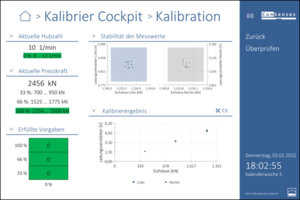
The symmetrical measurements are typically the standardized tool for our customers for the calibration of system sensors, e.g. for the production of reliable machine overload protection. They are supported by the automated fingerprint software in the calibration cockpit of ConSenses GmbH. Users are guided through the process fully automatically.
The off-center load measurements are strongly dependent on the plant and application, here a specific test procedure is defined in each case, which is then regularly used for several plants of a manufacturer / operator.
Instrumentation and Measurement Methods
| ID | Measurement variable | Sensor | Measurement location | Typical measured values |
| 1 | Reference force sensor | Kraftaufnehmer, die in Summe die An-lagennominalkraft tragen können | Im Pressraum | F (kN) |
| 2 | Displacement/Position Sensor | Magnetostrictive Position Encoders | Between frame, ram | z (µm) |
| 3 | Accelerometer | Accelerometers | On the ram | g (m/s²) |
| 4 | Force Sensing (Plant) | PiezoBolts or existing system force sensing | In pressure column or on the frame | F (kN) |
Importance of fingerprint data
On the one hand, fingerprint data describes the technical capacity of plants under nominal encumbrances. In practical terms, the following conclusions can regularly be derived:
One system shows conspicuous tilting tendencies around the x- and y-axis.
- In this case, after consulting the machine manufacturer, an inspection of the guide system may be indicated.
- Tilting under the stroke can lead to service life and quality problems, especially in cutting operations with narrow cutting gaps. A tilt measurement during the process can help to ensure this. The fingerprint can be used to determine the permissible off-center force for adjusting tilts. This gives the toolmaker extended information on the gradation of tools and adjustment of spring packages.
One system shows low attenuation after impact / release from the reference load cells.
- Such machine properties can be critical, especially in the case of impulse-like process events, because oscillation cycles are introduced into the structure without damping and can thus ignite aging effects at an early stage through interplay.
- In the case of slow-running processes, large impact events can occur, e.g. cutting impacts, touchdowns and the acceleration of large hold-downs in the return stroke.
Evaluation of the system stiffness and force build-up:
- Mechanical presses, while neglecting the flywheel mass effects of the ram mass, can only generate the required force effect through their elastic behavior.
- Typical compliance (1/c) of mechanical presses is roughly in the range of 0.1 mm / 1 kN.
- In the overall context, the fingerprint methodology also allows to estimate the force build-up in the process, because the ram mass and impact velocity (calculated from position data)
By comparing such parameters, the suitable machine for a particular forming process can be selected and potential areas for optimization can be identified at the same time.
Strengths and limitations of fingerprint methodology
| ID | Strengths | Known boundaries |
| 1 | Statistically backed up | Measurement is methodologically carried out around the LDC/FDC |
| 2 | Can be implemented regardless of the machine type | The system must be able to run in automatic operation without trans-fer and conveyor system. |
| 3 | Largely automatable | |
| 4 | Proven to be highly repeatable | |
| 5 | Proven to be comparable | |
| 6 | Implementable for users | |
| 7 | Well interpretable physically |
Quality Control
The fingerprint provides a baseline for the expected mechanical performance of systems. For this reason, press manufacturers use our fingerprint for internal machine acceptance and calibration of the installed measurement technology. In addition, operators regularly check their systems with fingerprints they have carried out themselves or supported.
Process optimization
Since the fingerprint reflects the individual characteristics of the tested systems, they are often used to coordinate processes in detail with machines.
Machine Design
In the design of new forming machines, the fingerprint data is used as measured and target values. This means that machine designs for specific application portfolios are described in the form of fingerprint results and design elements are designed in such a way that a tailor-made solution is created. The achievement of the target is then checked via the practical fingerprint creation.
Predictive Maintenance
Operators can use the fingerprint data to derive forecasts for the remaining service life of a machine. Sudden changes are indications of leading, bearing or other damage. Due to the physical significance and temporal resolution of the values, it is also possible to identify locations of damage and, in the context of process fingerprints, the causes of damage.
Consequently, loads are then reduced on the basis of these findings and processes are thus operated in a more system-friendly manner.